Brain Pong
play pong with your eyes!
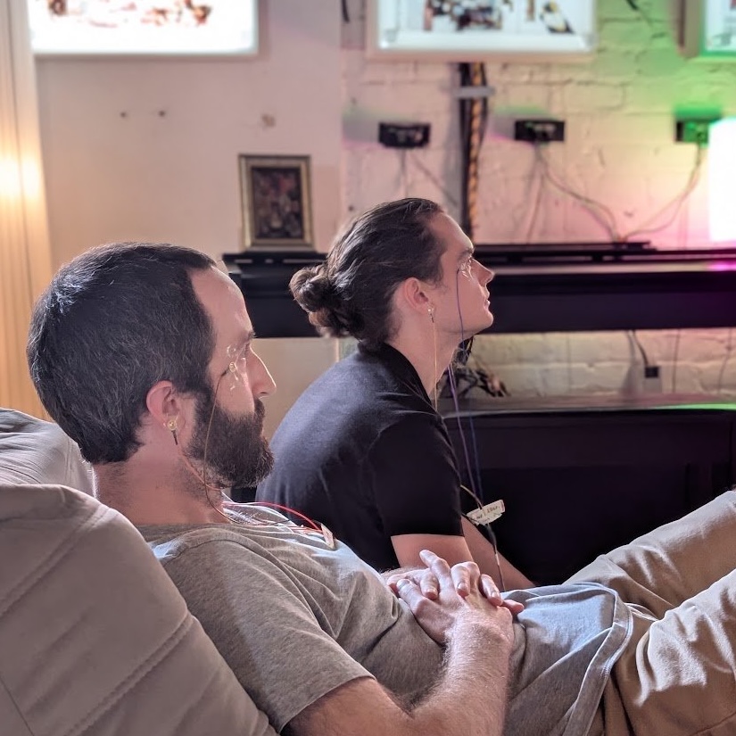
part 1: actions
ocular origins
My first BCI was properly medieval. 6 saltwater sponges were held together with a plastic headband.
🔓 Hardware Unlocked: Saltwater sponge electrodes
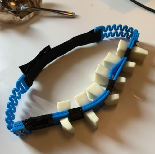
Electrodes are any material that conducts an electrical signal from one place to another. Saltwater is conductive, so when sponges are placed firmly against the skull, faint electrical signals from the brain can be picked up. Wires stuck into these sponges read these signals into a computer.
I mixed the saltwater by hand, adding generous amounts of sea salt to a bowl of warm water. The whole headband was dunked into the bowl to wet the sponges. The sponges sat near the back of the head to give them good contact with the occipital lobe. They were rudimentary EEG electrodes. However, this did little to mitigate the feeling of water dripping down your back. Only brave souls not afraid of a little water would wear it.
The headband still needed to be plugged into a Cerelog BCI board.
🔓Hardware Unlocked: Cerelog 8-channel BCI board
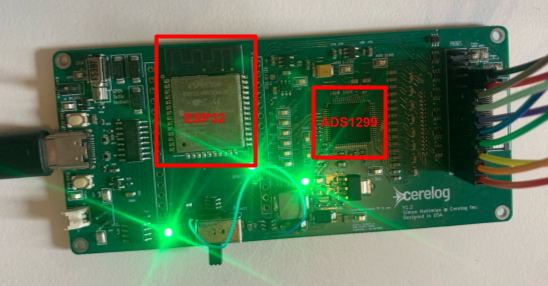
A Cerelog board has two primary chips: an ESP32 and an ADS1299. The ESP32 is the “brains” of the board: it has a CPU core, some memory, and integrated wifi/bluetooth. Helpful for any small hardware system. The ADS1299 is what makes this a BCI board. It has many useful pins, most notably 8 electrode inputs, an SRB1 input, and a bias output. More on these pins later.
The board converts signals from analog to digital and gives my computer access to those values. Once the values were connected to the Pong script, the game could be played.
I inherited the device from a previous intern while interning at Cerelog, a BCI board design company. The intern had built the headband, and wrote software using SSVEP that analyzed the signals coming from the sponge electrodes. Flashing lights were on either side of the pong screen; the left flashed at 15 Hz and the right flashed at 10 Hz. How was looking at flashing lights converted into controls for Pong?
SSVEP Explainer
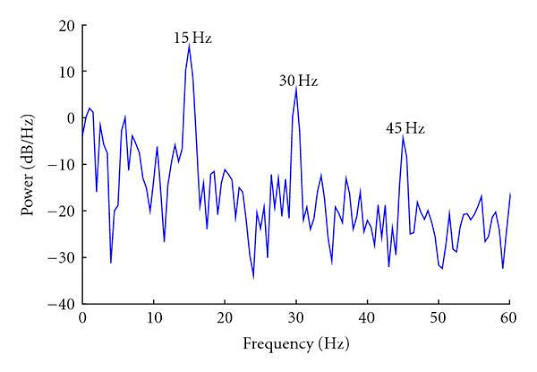
Looking at the graph above, I would claim that the subject is currently looking at a 15 Hz flashing light, not 10 Hz. When the eyes are stimulated by a light flashing at a certain frequency, the neurons of the occipital lobe (the portion of the brain processing sight) pulse at that same frequency. The neurons’ signal can be measured with electrodes. When you examine the frequencies of the electrode signal via FFT, there is a clear spike at the frequency of the flashing lights (in this case 15 Hz). There are also harmonic effects, which is why you see spikes at 30 Hz and 45 Hz.
At this point, you may ask: how well did this work? Decently. It also had some problems. If I focused intently on one side, I could usually move the paddle left or right. However, this was contact-dependent: a guy with a near-shaved head was able to control it reliably, while a girl with thick hair found it basically unplayable. Staring at flashing lights gets painful pretty quickly too.
Kudos to the prior intern for making it work! It was technically impressive and helped lay a foundation of understanding for my future work.
dashing to a demo
I felt I could build a more reliable BCI, and set out looking for other options.
Simplicity was important to me. I wanted to prove I could build a BCI at all, without worrying about the usefulness of the device yet. Through research, EOG emerged as the clear frontrunner.
EOG Explainer
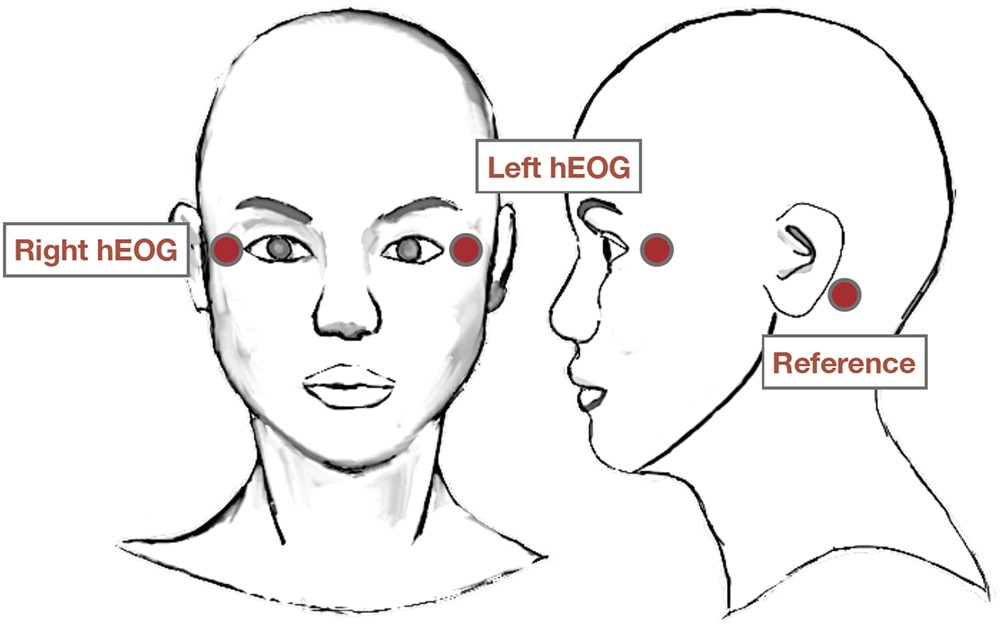
EOG is a method of recording the electrical signals created by eyeball movements. There are additional things that cause electrical activity around this region of the face like blinking or swallowing. An eyeball is charged; it has a positive charge in the front and a negative charge in the back. When an eyeball swings left, nearby electrodes can record a spike in voltage. Whether the spike is positive or negative is determined by whether the person has looked right or left.
The signals from EOG are clear, large enough, and correspond to known actions. In contrast, EEG signals don’t have a clear 1:1 mapping between actions and signals.
I also got my hands on a set of gold electrodes.
🔓Hardware Unlocked: Gold Cup Electrodes
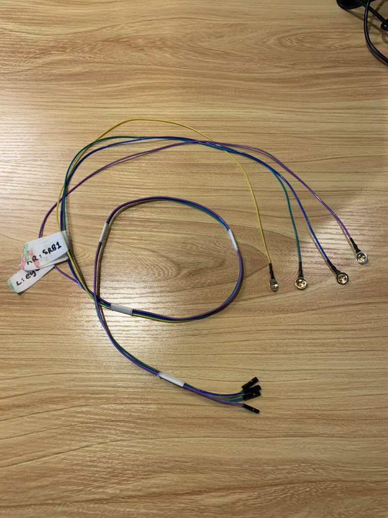
Gold cup electrodes serve the same purpose as saltwater sponge electrodes: conduct signal. They have several advantages. Their impedance (similar to electrical resistance) is low when combined with proper skin preparation and Ten20 conductive gel. The gold plating also resists corrosion, meaning they last longer and can be regularly washed and reused. In absolute terms, gold has worse impedance than silver/silver chloride electrodes (and perhaps even the sponge electrodes? didn’t test). However, the gold electrodes have worked well for me so far.
Honestly, the reason I bought these is because OpenBCI recommends them on their site. I’d seen successful products using an OpenBCI board in the past and had confidence the electrodes would work well enough for my purposes.
I’m going to make a claim up front and then explain step by step how to get there. Stay with me.
Using these pieces and a couple more tricks, when the eyes move, a clear spike can be detected in the data.
There were lots of bumps on the way to detecting a clear spike. By the end of this, you should understand how every step of the pipeline works.
1. the man looks right
Pretty straightforward so far.
2. raw electrode traces are measured
My body is a big bag of salt water. It’s fantastic at picking up signals. When an electrode is placed on my skin, the following are some biological sources of voltage: brain activity, jaw clenching, blinking, swallowing, talking. The body is also fantastic at picking up signals from the environment; here are some non-biological sources: power outlets, computer charger transformers, large speakers, power tools, large machinery like refrigerators. Power outlets are the worst offenders. They produce a large 60 Hz wave (50 Hz for our European friends) that is in the mV to V range; significantly larger than the signal we’re looking for. In contrast, eyeball movements create signals measured in the µV range. To get useful signal, we need to remove the environmental noise.
EOG’s standard technique is to use a reference electrode, in our case called an SRB1. This electrode’s purpose is to set an electrical baseline by attaching to the body in a place we don’t care about and measuring the “background” electrical noise. This noise will be both biological and non-biological in nature. If you’re sitting near an outlet and also swallowing, this reference electrode would pick up some combination 60 Hz wave + throat muscle signals. Another electrode close to the eye would pick up something similar: 60 Hz wave + throat muscle signals + eyeball movement signals. The reference electrode wouldn’t pick up the eyeball movement because those signals are very weak, so they don’t travel very far.
In my example, I’ve set the “background” noise to 60 Hz plus some extra harmonics. 3 electrodes on the body measure signal: left eye, right eye, and reference electrode, as shown in the EOG picture above. These electrodes that measure signal are called passive electrodes. As you can see, when the SRB1 signal is subtracted, the signal range drops from Vs to mVs. This is good and expected.
3. bias is driven into the body
Bias is the 4th electrode, attached to an earlobe like SRB1. Bias doesn’t record anything, it sends an electrical signal back into the body. This is called an active electrode.
What signal does it send? There’s still noise in the left eye and right eye electrodes. The ADS1299 calculates the average signal between the two electrodes and pumps it back into the body via the bias electrode. This signal is in the mV range and shouldn’t hurt anyone. Most of this noise is common mode noise. The bias helps drive the body’s common mode noise close to zero volts so that the measured signals are within the chip’s measurable rails.
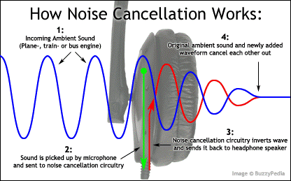
This works on the same principle as noise-cancelling headphones: active interference. When a wave and the exact opposite wave are played at the same time, they cancel out. In our case, the difference we’re left with is the faint signals of the two eyes.
4. digitization
The real-world analog values are now converted into digital ones. This is done using an ADC.
ADC Explainer
An Analog-Digital Converter, as the name suggests, takes analog signals and converts them to digital ones.
What are these signal types? Analog signals have continuous times and values, meaning the signal has some exact value at an exact time. A beach wave has a position at 3pm, but also at 3:01pm, 3:01pm and 1 second, 3:01 and 1.1 seconds, and so on. The time can be sliced infinitely small (some physicists may contest this) and the beach wave’s position will change smoothly with those time jumps.
Digital signals do not have this freedom. They have discrete values: a computer can only record times and values to a given precision. With more memory, a computer can increase the precision of their representation, but this precision will always have a limit.
When an analog signal is converted into a digital one, the values must be “bucketed”. The simplest way to do this is: for each time step, measure the analog signal’s value and assign it the closest digital value the hardware can represent.
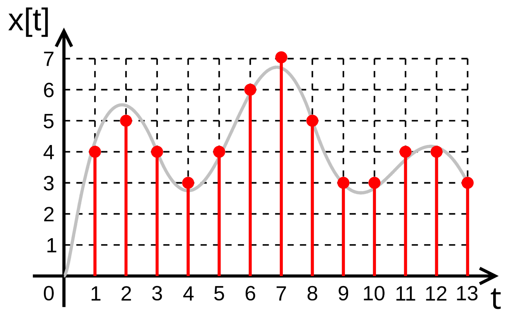
In the above image, the digital representation can represent whole numbers. At t = 11, the “true” signal value is around 3.75. The computer can only store whole numbers, so the digital representation of 3.75 is 4.
My Cerelog board samples at 250 Hz (it can sample faster but the data output becomes a problem). However, in this animation, we’re sampling at 10 Hz because it’s easier to see. The analog data is converted via the board to a 24 bit value.
All of this so far has been done on hardware, primarily the ADS1299 chip. Once digitization is finished, the values are sent off to the computer to be processed by software. All future steps are done in software.
5. subtract left from right
We now have 2 raw data channels: the left and right electrodes. We don’t particularly care about the exact reading of right or left, but the difference between them.
Remember the idea underlying EOG: The eyes are charged. When the eyes swing right, one eye is moving towards an electrode, and the other is moving away. We should expect to see a positive change in one channel and a negative change in the other. When subtracted, this should show clear directional swings after looking left or right.
6. detrend
The left and right electrode voltages have a tendency to drift over time. This is due to gel drying, the exact contact shifting, and some electrical effects. These factors are usually slightly different across electrodes, leading to them drifting different amounts. Even after the two channels are subtracted from each other, there can still be a noticeable slope over time, shown in the image below.
Detrend takes the gradual, zoomed-out slope of a graph and flattens it to zero. It also has the added benefit of setting the y-axis value of the signal to zero, which can be helpful for filtering.
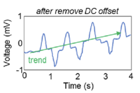
My detrend is very aggressive. It flattens the signal more than I’d want. I’d like to adjust it to take effect over a period of 10 seconds instead of the ~0.5 seconds it takes to bring the signal’s value to zero.
Notice also how detrend also brings the graph’s vertical offset to zero. This makes applying future math easier.
7. perform filtering
Even after the board filtered out some of the high-frequency noise, a lot still remains. This noise makes it harder to isolate the signal, so it’s worthwhile to strip it out. The standard industry tools are filters that snip parts of the frequency range. I use a low-pass filter at 100 Hz, high-pass filter at 0.5 Hz, and band-stop filters at 50 Hz (European) and 60 Hz (American).
Other than the band-pass filtering for specific wall outlet frequencies, picking precise numbers was an exercise in the dark arts. I reviewed the literature a bit, looked at what worked a bit, and held my finger to the wind a bit. 0.5 and 100 Hz seem to work well.
8. perform calibration
Finally, we’ve made it to what I would judge to be a somewhat “clean” signal. Notice all of those spikes that have popped out? Those indicate clear left and right motions of the eyes.
How do we judge what counts as a spike? Spikes can vary by height. A simple way is to plop the subject in the chair, wire them up to the electrodes, turn on the software, and record them for several seconds. It’s good to ask them not to move their head, blink, swallow, or look around. This establishes a clean electrical “baseline”, aka a “noise floor”. We can derive a sigma value that defines a “noisyness” for their data.
I use the following median absolute deviation formula to calculate the exact sigma value:
σ = 1.4826 × MAD
9. detect spikes
We use the sigma value multiplied by some constant to establish lines above and below the zero line. If the graph crosses it, congrats! Spike detected.
This is the entire output of the processing pipeline: a series of positive and negative spikes (both red but recorded differently) at various timestamps. We can now use these spikes to drive the Pong paddle.
The control scheme is a little wonky: when a left spike is followed by a right spike in a certain window, the paddle moves left (vice versa with right followed by left). This is done because live detection of eye angle seemed tricky to detect, and large left/right eye movements seemed easy. However, if you want to move your paddle left 3 times, looking further left 3 times might rotate your eyes out of your skull. Thus, the “glance pair” was born: look left and then back to center to move the paddle left.
This was the basic setup that allowed me to get Pong working for the very first time. The resulting pipeline was noisy, but the game worked. It was a surreal feeling to control something with my mind for the first time.
Fair warning: The hardware noise in these animations is a guess. The software signals from the “subtract left from right” animation onwards are real recordings from my own R/L electrodes. I took a guess at reasonable environmental noise and extrapolated backwards for animations 1-4. The SRB1 and Bias data are spoofed to common frequencies and amplitudes; the real ADC sampling is significantly faster (250 Hz). All the math, however, is real.
path of pain
After the initial success of the pipeline, I got cocky. The pipeline still had bugs but I wanted to optimize.
The SRB1 pin, as mentioned earlier, provides an electrical baseline. Measurements against it provide the electrical baseline your whole body is at so that this value can be subtracted out from individual left and right electrodes. SRB1 is subtracted from both left and right. That means that when I subtract left from right to create a single wave, the subtraction of SRB1 from both should cancel out. It seemed like an unnecessary part, so I thought deleting it would simplify the system. In practice, it led to more pain.
Once I removed SRB1, all of my data was garbage. It was noisy and basically impossible to extract signal from.
There are two reasons for why it broke.
The first is relatively obvious: the electrodes needed it. Each electrode has a possible range of values that it can take, and if it goes too high (or low), the signal “rails”, meaning it can’t go higher. The recorded value flatlines. Subtracting SRB1 from each signal kept each signal individually within a healthy range so the signals would rail less often.
SRB1 is the ground from which the voltage is measured from. If the signal measures the top of a building, SRB1 measures the ground floor. When the SRB1 is removed, there’s no ground floor to measure against, so the height of the building is impossible to know. Voltage is measured relative to other voltages, not absolutely.
The second reason is actually unrelated to SRB1. When changing the firmware to ignore SRB1 (aka differential input mode), I accidentally turned on all 8 channels as input to the bias signal (via firmware). Previously, the bias was only calculated from the left and right electrode channels. This means that when the bias was calculating which signal average to generate, it used 2 channels of real signal and 6 channels of garbage unconnected electrical noise (nothing was connected to channels 3-8).
Imagine trying to listen to 2 people singing together, but then 6 other people start screaming at the tops of their lungs. They are not helping!
This made the bias signal mostly garbage, which fed back into the head and made the left and right channel data garbage too.
Even after I turned SRB1 back on, the signal still didn’t improve. I went a little crazy considering a whole host of theories for why my data was garbage. My raw data was noisy, so most of them related to connection quality, like:
- the body – electrode connection is bad
- the electrode – board connection is bad
- the board – computer connection is bad
I tested these theories one by one. The culprit (as the reader knows) is none of them, but I’ll talk more about them soon.
After a while of pulling out my hair, I took another look at the firmware and discovered the 8-channel bias error. It was a simple fix to drop bias back to 2 channels and reflash the board.
Things will always break; this is a normal part of the iteration process. Upon reflection, the key error of this process was not understanding the firmware I was using. I had skimmed the ADS1299 datasheet but hadn’t understood there was a setting for modifying the channels bias used in calculation. My agent made software changes that I didn’t understand, and I had to understand the firmware fully to fix it. You could also argue that giving the agent more context on how I was using the board may also have prevented this.
I also committed the sin of optimizing too early. I shouldn’t have tried to change things that weren’t on the critical path. The SRB1 electrode wasn’t hurting anyone. A clearer articulation of this problem is given by the story of the Monkey and the Pedestal.
In future projects, I want the software to spit out its firmware configuration on boot and check that it matches the desired firmware. I will also be reading through the ADS1299 configuration settings again.
incremental improvements
I mentioned earlier that my paranoia generated many theories for why my data looked like garbage. None of these on their own were transformative, but led to small improvements that I appreciate anyways. I’ll go through them quickly.
body – electrode connection
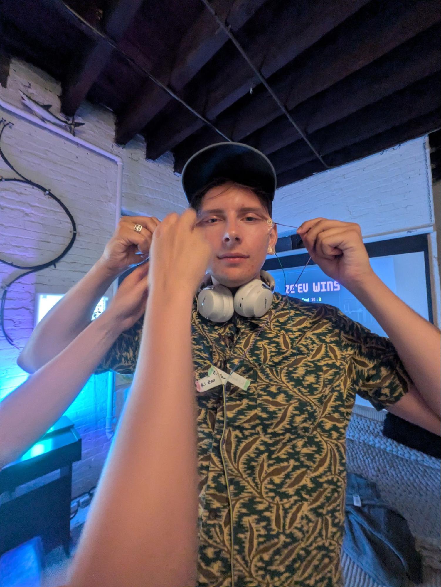
Ideally, all electrodes will have both a low and a similar impedance. If one electrode has a different impedance, the chip cannot fully reject common-mode interference (especially from 60 Hz mains).
Originally, I directly applied gelled electrodes to the head. Now, my protocol calls for skin and gel standardization:
- ask subject to wash face with soap (sweat changes conductivity)
- abrade subject’s skin in electrode spots with paper towel
- clean subject’s skin with alcohol
- apply gel to each electrode. eyeball for standardization
electrode – board connection
This is a fancy way of asking “are the wires good?” I used an ohmmeter to measure all of the wires I was using. I found that 1 of 4 had higher resistance than I expected, cut the wires and rewired it, and the resistance dropped to nominal levels. Good wires will have resistance in the ohms - kiloohms range; megaohms means your wires are bad.
This problem was later negated by switching over fully to gold cup electrode wires. These were more reliable than hand-taped wires.
board – computer connection
The board sends the computer electrical signals to encode data. If anything else is electrically connected to the computer, it can interfere with the data transmission. Ideally, you can create an electrically isolated system of body and board and computer, with nothing else conductive touching this system.
After numerous gaffes of getting noisy data, I updated my pre-game checklist to include the following:
- disconnect laptop from charger, external monitors via HDMI, and all other cords that are not strictly necessary
- place body, board, and laptop on non-conductive surfaces
These changes largely solved their associated noise issues.
gathering gigabytes
The path to improvement appeared next to be mass data collection. I had the software working reasonably well on myself; surely I should collect data from lots of people and see if it worked on them.
The data collection script prompted people to look left or right randomly, and then back to center. They were wired up while they performed this task. For the most part, this data was very clean. Peaks were easy to see, noise was low, and the timestamp of when they were prompted to look was also recorded.
Useful software changes precipitated out of the new data. The largest glaring problem was that my amplitude detector was failing to capture a majority of the prompted glances in my new dataset. It had a 45% failure rate using a 6σ detection band when tested on the 10 new people. Amplitude filtering worked well on me, but when tested on others, it could fail spectacularly. This was obviously unworkable.
After a literature review, the obvious change was to switch from measuring amplitude to velocity. When someone looks left or right, there’s a very strong and fast spike in one direction and then a smaller reverse spike as the signal attenuates back to zero. Using a pure amplitude detector can sometimes pick up this reverse spike as its own spike. By using a velocity detector, the first faster spike is easier to pick up and the reverse spike can be discarded. This needed to be coupled with HPF/LPF value tweaks to make it work well on everyone.
As in the “detect spikes!” animation, all signals above and below the lines are recorded as spikes. These spikes are converted into paddle movements.
A fatal flaw existed in this method of data collection. It failed to replicate tournament conditions well. People blink, swallow, turn their head, look partially left, and move their eyes at different speeds. They’re fantastic at creating unwanted electrical noise. The process didn’t even consider two people, the actual gameplay format. Come tournament time, my pipeline would prove insufficient for some.
People were the highlight of this process. I wanted to collect 10 different datasets and didn’t consistently have 10 friends floating around the workspace. Cold-approaching strangers and asking them if they wanted to “get hooked up to my brain machine” was a lot of fun. I got several responses of “no” or “i’m busy”. Overall, I was surprised by how much people were willing to help me. Asking strangers for things usually goes pretty well! It’s nice to have a couple more friendly faces to say hi to in my workspace.
time for a tournament
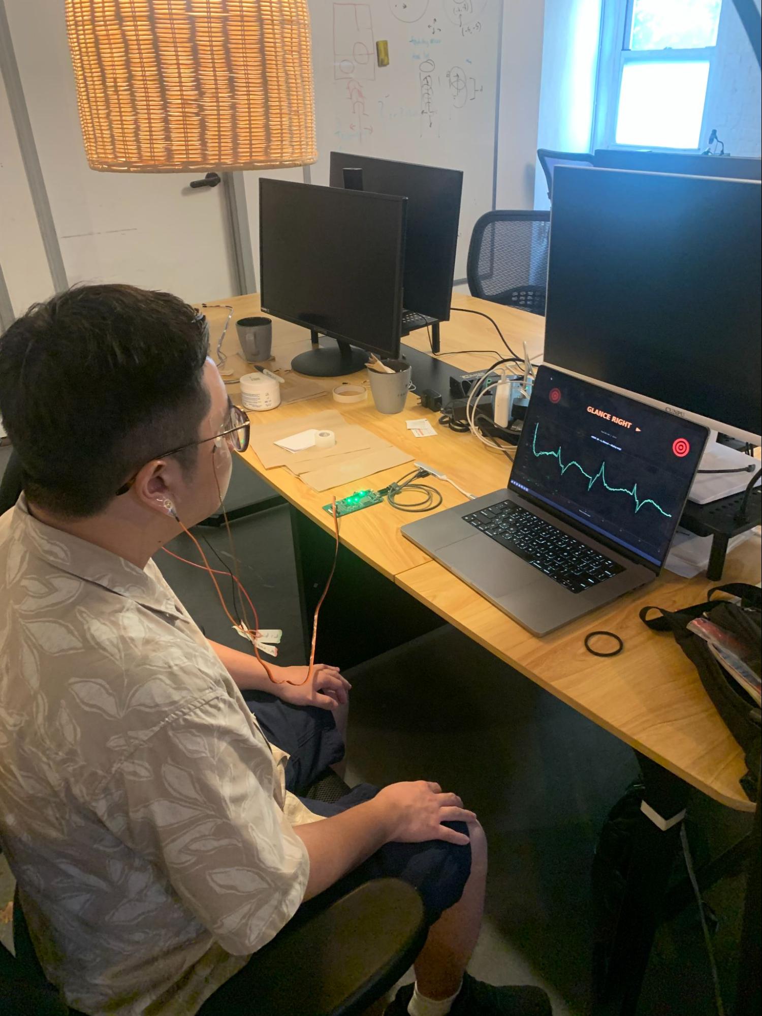
To finally put the technology to the test, I hosted a Brain Pong tournament. Everything was in place: the competitors had been signed up, the eyeball-shaped snacks had been purchased, and the electrodes had been labelled and dried. All that’s left is to see how the tech performed.
A problem I ran into is that everything took dramatically longer than I had expected. This had two parts: First, I hadn’t run a dress rehearsal, so the time spent gelling and alcohol swabbing and talking with contestants ballooned to much longer than I had planned. Ignore the golden rule of “everything always takes longer than you expect” at your own peril. Second, I ran into a lot of technical problems, primarily noise, that I had to do my best to mitigate. This also burned time. Even though I had conducted 2-player tests before, running it on many people revealed new problems.
There were some steps I took to mitigate tournament noise. Foolishly I tried again to see if an HDMI projector would work, as the center room had a nicer screen for tournaments. This failed and I switched to the sideroom wireless projector and used Screen Mirroring. This successfully reduced noise.
I also electrically isolated the contestants and board and computer. I put textbooks beneath the laptop and board, and swapped the contestants chairs from metal stools to a wooden piano bench.
Some contestants had dramatically more noise than others. This is still a mystery to me as to why this would be the case. Removing, regelling, and reapplying the electrodes didn’t help much.
The summer heat was bearing down on the contestants as they arrived at the tournament. Many of them showed up sweaty. I had a suspicion this was creating unnecessary noise recorded by the electrodes; asking them to wash their face with soap seemed to help.
Some contestants had fantastically low noise, while others basically couldn’t get a clear signal at all. Sometimes I feel like I’m taking crazy pills; that electrons hate me personally; that some people are secretly robots that have 10x the electrical noise from real humans. The process of getting better SNR across 10+ people has felt a bit like a knife fight in the dark, where only excessive paranoia and problem isolation allows me to make progress. Any way I can lower the odds of a problem occurring is a gift.
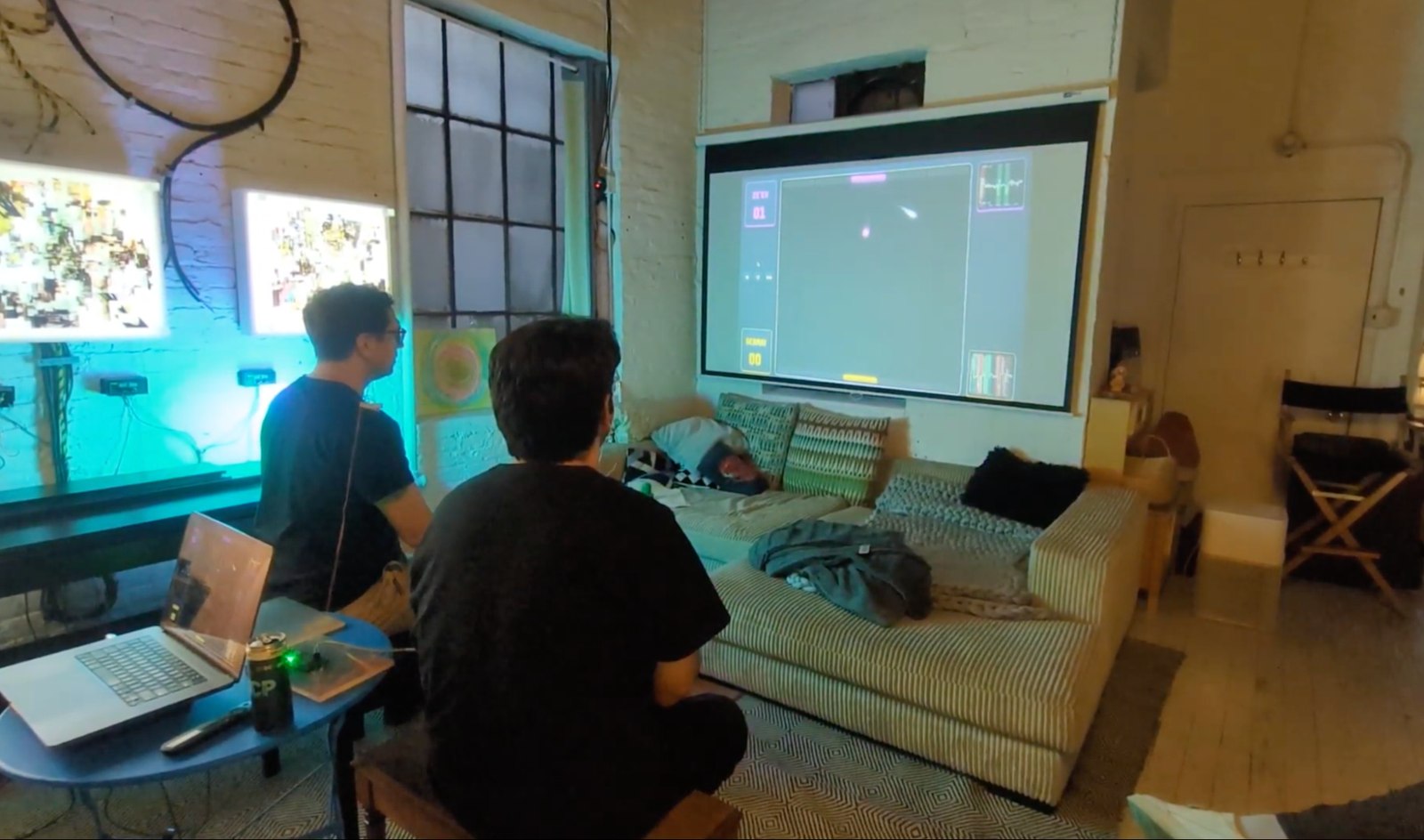
The people and conversations that night were a high point! Neuroengineers of all stripes turned up that night. We had in attendance:
- the founder of Cerelog, the company designing the BCI boards I use
- the founder of a TMS company
- the founder of a non-invasive BCI headset for ADHD and autism
- a member of a neuroscience research group
- an intern from a VC fund interested in BCIs
- several neuro enthusiasts, excited to incorporate BCI tools into their workflow
- many friends, who were very supportive and loved chatting about the brain :)
As the pong games raged on, it was a joy to hear snippets of neuroscience discussions in the background.
The tournament was chaotic. The technology worked smoothly on probably less than 50% of people. It’s frustrating when the controller doesn’t respond as you expect it to. When I throw the next tournament, game control accuracy is my biggest focus. I want people to be able to feel like they’re in control.
In other ways, the tournament was a smashing success! I’m grateful so many competitors wanted to play and gave me an excellent opportunity to test the technology under real-world conditions. The wealth of data I’ve collected from the tournament should help me refine the processing pipeline further. Bringing BCI-interested people together was also a blast.
So long; I hope you liked the eyeball-shaped snacks!
part 2: reflections
how did I screw up?
How could I have conducted this process better, from prototype to tournament? It’s traditional to conduct a post-mortem after software incidents (Crowdstrike 2024), and the military conducts hot washes after missions. I want to take some time to reflect on how to do better.

My greatest sin was not sprinting to a full integrated test. I had a working one-player version in May! When one-player was working, I should have immediately modified the game to support two-player and tested it until it broke. Integrated tests usually reveal major problems, and I should have tried to find these problems as soon as possible.
I treated two-player, the actual use case, as an afterthought. It burned me. I did one test with another person a day or two before the tournament that seemed to go well, but the full tournament with 8 new people revealed massive noise problems. Iteration speed on the critical path is often the bottleneck; build the next version quickly!
On my next project, I’ll specify a series of progressively harder tests to run. They’ll start with very simple tests (does the board turn on?) and culminate in the full integrated test. Then, I can ruthlessly knock out successful tests and keep my eye on the final test.
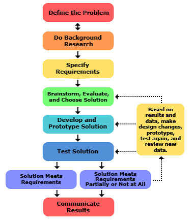
My second greatest sin was not following the engineering design process. I was thrashing around trying to make progress without defining a goal or using metrics to guide my decisions. Many of my decisions were based on vibes. There is a wealth of EOG literature that I, at best, skimmed. This existing literature may have shown me easy solutions to problems I was having. This includes reading the ADS1299 datasheet too; there’s an option to output the bias signal that I totally missed.
Letting my decisions be driven by requirements and metrics likely would’ve forced me to understand the technology more deeply. Poking at problems as they arise isn’t a strategy (although organizational firefighting can often be good). The closest I got to using requirements was using true positive/false positive/false negative rates to drive algorithm decisions. This was reasonable but unstructured.
On my next project, I’ll make a point to explicitly do each step and document my results at each step. This will force me to not only do the work, but come to a legible decision at each step, so I can’t throw my hands up and say “ok, that’s probably enough brainstorming. on to the prototype!”
Admittedly, these problems are at odds with each other. I should sprint, and also follow a structured engineering process? Yes. I need to go faster and also learn what structure is helpful; progress is possible. Continuing to build and look for ways to improve is the only path to grow.
There were other failures which were not as critical but are worth mentioning.
I wrote basically 100% of this project with AI tools. Like many other developers, I haven’t written a line of code by hand for a while. I should have given the agent environment more attention; this would have been a major force multiplier for coding progress. This mostly involves leaning into the Bitter Lesson: general methods outperform structured-but-limiting ones in the long run. Give your agents more context about you, your project, and your desired workflow. Remove requests for your agents to work in a certain way unless it consistently gets things wrong (but check again in another 6 months). More context; fewer limitations. Follow @__drewface or @___Atin___ on twitter if you want to supercharge your agent workflow! While I did use LLMs to code this project, I’m not convinced that the time of hand-written software for safety-critical systems like BCIs is over. However, the industry seems to be moving towards AI systems that supercharge testing and observability of code instead of more human effort.
I should have built more internal tooling. Specifically, an automated test suite, live quality tests for firmware and electrode quality, and a data visualization pipeline to view every data transformation step would’ve helped. I’m making the assumption that this tooling would tighten the iteration loop by providing additional visibility to what specifically was failing.
The data processing pipeline also had no personalization to individuals. People have different noise and signal characteristics. This honestly might be fine with simpler artifacts, but I have a hunch this will fail horribly if I want to make the jump to 8-channel EEG. A better approach would be to build an ML model, either generalized or tuned to each individual. This would cost more time but lead to better results.
what’s next?
EOG is cool, but it isn’t measuring the brain. It measures the physical motion of the eyeballs. It was a good technology to build basic skills, but I want to level up to measuring the brain directly.
My next project will likely be an EEG mouse. I’d like to get familiar with brain signals, as I’m actively pursuing employment with brain interface companies. A mouse provides two degrees of freedom + click, opening up more games than just the one dimension of control of pong. Think of all of your favorite games that can be played with just a mouse. 8-channel EEG will have significantly more and weaker signals than 2-channel brain pong, so I’ll have to learn even more tricks to get it to work.
I want to close with a final note on safety. My level of rigor for this first engineering artifact is acceptable to me, as it was never going into anyone’s head and the voltages were low. As a first BCI, I’m comfortable with the philosophy of “make it work at all”. This isn’t acceptable for future invasive BCIs.
If I intend to help build implantable devices, the safety and reliability need to be bulletproof. The most useful instinct here is paranoia. It is worthwhile to try literally anything to decrease the risk of devices failing their seal or behaving erratically or being hacked.
Testing the shit out of the device before it comes close to human implantation is an obvious must. Simulated and vat-grown brain tissue testing is probably smart, and animal studies are regrettable but necessary. I’m also a big fan of restricting the software and hardware used to only be able to do what you want and literally nothing else. The designs of Science Corporation and Precision Neuroscience are also fantastic as they never directly insert anything into the cortex, just place electrodes on top. I would even advocate for a system similar to the airline industry, where all commercial crashes are investigated.
If the industry continues down its current path, significantly stronger safety controls will be necessary.
why do this at all?
The human brain is a glorious mystery: the originator of all experiences and yet a confusing mess of connections that we don’t fully understand.
In the short term, there is an enormous amount of medical good to do. Sensor/actuator problems, i.e. the brain’s failure to communicate with sensors like eyeballs or actuators like muscles, seem firmly in reach with enough capital and engineering effort. Brain implants are already restoring capability to quadriplegics and close to restoring sight. Progress will continue and the health and capability of those we love will improve.
In the long term, things get more speculative and exotic. How could we improve the human condition if we unlock general read/write capabilities to the brain? Communicate without words? Add senses? Plumb the depths of how our minds really work? Merge with machines? The possibilities dizzy me.
It is not a riskless path. Having a computer connected to a mind surfaces questions of privacy, of exotic failures, of brain hacking. These are very scary futures, and ones I would like to steer away from in the strongest terms. I will always work for humanity.
Let’s build a beautiful future together ❤️
glossary
- ADC: analog-digital converter
- ADHD: Attention-Deficit/Hyperactivity Disorder
- AI: artificial intelligence
- BCI: brain-computer interface
- CPU: central processing unit
- EEG: Electroencephalography
- EOG: Electrooculography
- FFT: fast fourier transform
- garbage: a technical term for Very Noisy Data
- HPF: high pass filter
- LPF: low pass filter
- ML: machine learning
- mV: millivolts
- µV: microvolts
- R/L: right/left
- σ: sigma, used in context for standard deviation
- SNR: signal-noise ratio
- SRB1: stimulus/reference/bias pin 1; a pin of the ADS1299 chip
- SSVEP: Steady state visually evoked potential
- TMS: Transcranial magnetic stimulation
- V: volts
- VC: venture capital
- Hz: hertz
acknowledgements
Thank you to Esther, Simon, and Lily for helping review this essay. They helped correct technical details and pointed out where people outside the industry might stumble. I’m very grateful for their help.